This example shows how to model a 6-axis industrial robot arm from scratch, using the 3D models provided by the manufacturer.
Follow these steps to gather some information about your robot:
1.Firstly, you need the 3D models (such as STEP or IGES files).
2.You will also need the robot data sheet or robot manual.
Follow these steps in RoboDK to open the robot model window:
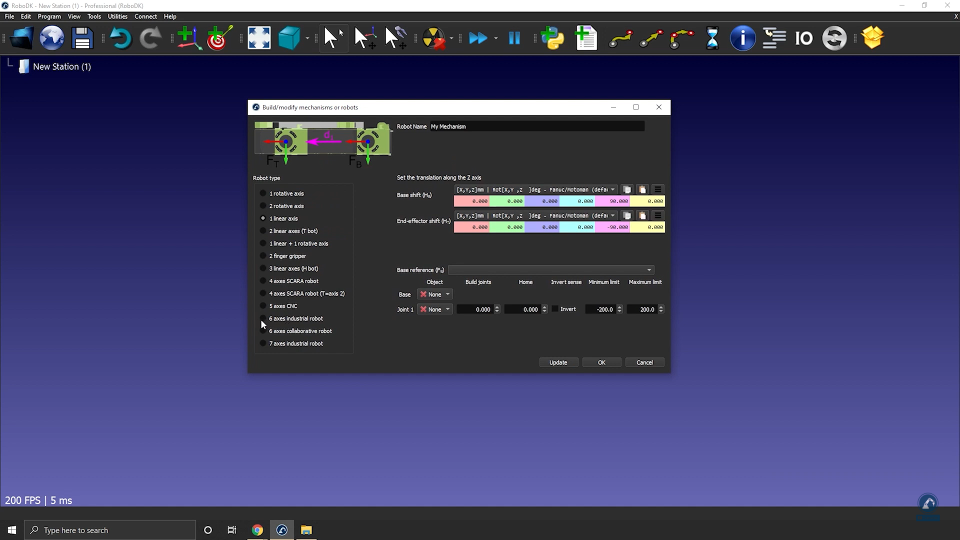
3.Select Utilities➔Model Mechanism or Robot.
4.Under Robot Type, select 6 axis industrial robot.

Load your robot 3D files onto RoboDK by doing the following:
5.Drag and drop your robot into RoboDK or select file and then open (it may take a few seconds to load).
Follow these steps to split an object into different pieces so that we can treat each piece separately:
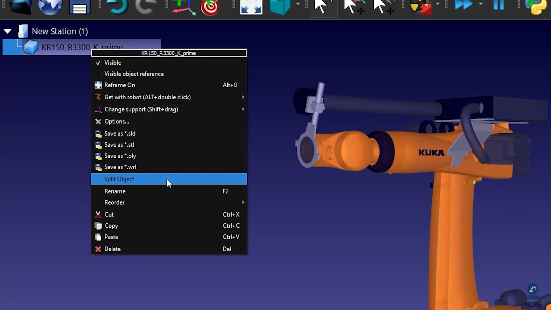
6.If the CAD file that you downloaded is in one single object, you can ungroup the object (STEP file) by right-clicking on any object and selecting Split Object.

7.You can then regroup it to create the different pieces of the robot.
Follow these steps to enter the robot kinematics information in RoboDK:
8.Give your robot a name by entering it in Robot Name.
9.If the pieces of your robot are in the right order, then all of the 3D models should be populated correctly. Otherwise, you can manually link each object to the right robot joint.
10. Fill in the dimensions of the robot by opening the data sheet.
11. On the 3D sketch of the data sheet, you will find all the values that you are looking for. Fill in the correct values in RoboDK.

12. Once you are satisfied with the result of the robot kinematics, select Update.
Some robots have two joints coupled together, which means that two of the joints of the robot are dependent. For instance, Fanuc robots have joint 2 and joint 3 linked together.
Follow these steps to couple the joints of your robot in RoboDK:
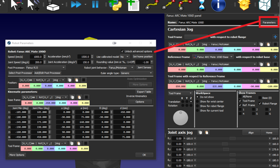
1.First, double click on the robot to open robot panel.
2.Click on Parameters to open the Robot Parameters tab.

3.Check the Unlock advanced options box.
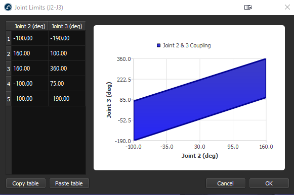
4.Click on Joint Senses to open the Joint axis sense tab. The first 6 values represent the joints turning direction and the last value is the coupling of joint 2 and 3. Change the 7th value to -1 to link the joints. A new tab with the coupling joint limit polygon will open, you can edit the limits to prevent the robot from colliding with itself.
